UART Essential for Pentester
PREAMBLE
The content of this blog post was originally a mini-talk with demonstration about UART in the context of pentesting. I therefore decided to transcribe the contents of the slides and add a practical demonstration.
INGREDIENTS (tools)
Before starting with the theory, here is a list of the tools:
- Router DLink DSL-2740B (an old one that I find in my garage)
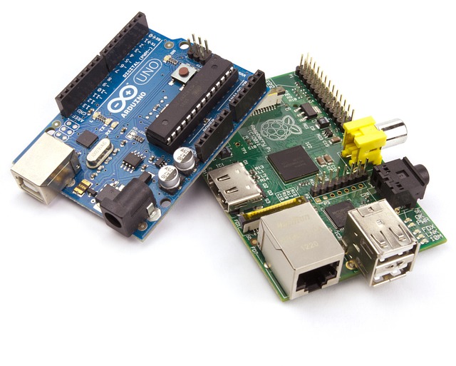
- USB to TTL Converter chipset FT232RL (you can use other chipset and also you don’t need one if you already have a BUS PIRATE, Shikra, HydraBus, Attify Badge etc…)
- Jumper wires
- Multimeter (logic analyzer or oscilloscope are expensive but more accurate)
UART
Universal Asynchronous ReceiverTransmitter (UART)
Is one of the simplest serial protocols mainly used for debug by vendors (threat vector for getting a shell).
Could be find in many embedded and IoT devices
UART transmit data asynchronously, which means there is no clock signal to synchronize the output of bits from the transmitting UART to the sampling of bits by the receiving UART. Instead of a clock signal, the transmitting UART adds start and stop bits to the data packet being transferred.
HOW IT WORKS

The line is held high (at a logical 1 value) while UART is in the idle state. The transmitter sends a start bit to the receiver, during which the signal is held low (at a logical 0 value). The transmitter then sends five to eight data bits containing the actual message, followed by an optional parity bit and one or two stop bits (with a logical 1 value), depending on the configuration. The parity bit, used for error checking, is rarely seen in practice. The stop bit (or bits) signify the end of transmission. The most common configuration is often referred as 8N1: eight data bits, no parity bit, and one stop bit. Now let’s go into practice
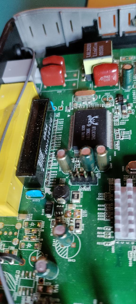
PIN ON THE BOARD
If you don’t have the datasheet of the board, they could be marked as “UART” or could be find single pin “TX” “RX” “GND” “VCC” or similar… Sometimes UART is provided through GPIO pins. It is also common not to have any identifying lettering. In any case try to look for exposed pins or four through-hole pads next to each other.
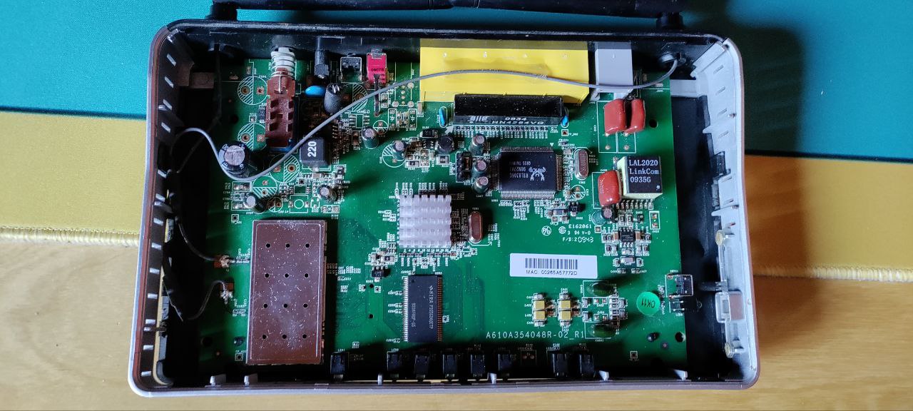
If you don’t have any information about what PIN is what, you have to find by yourself. Let’s do it!
WARNING
Remember to disconnect the router from the power initially. Do not touch the board and its components directly or with driver material.
IDENTIFY THE GROUND
Start by identifying the ground PIN. This could be done with a continuity test. So take a multimeter and test every pin. Keep one probe (conv. black) on a metallic surface, since those are usually shorted as ground. With the other probe (conv. red) start testing every PIN.
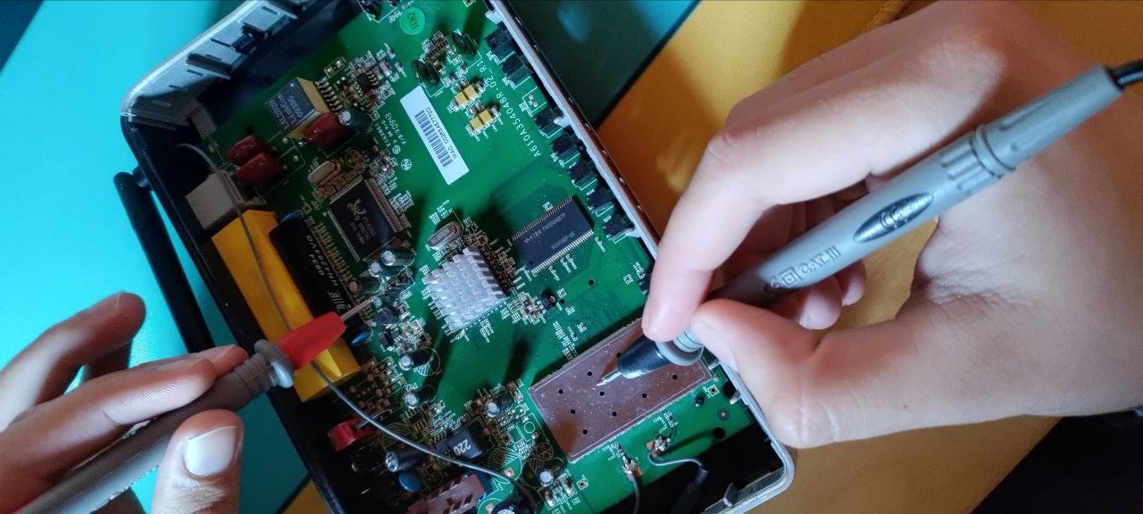
NOTE: I just said that “usually” internal metal surfaces are grounded. That it’s true but in my experience I found some devices that doesn’t have every piece of metal grounded. I highly suggest to test different metal surfaces. You can also try to touch 2 different pieces of metal and see if they are connected, if so they are probably grounded.
IDENTIFY THE TRANSMITTER
There are several ways to identify the transmitter PIN. The basic idea is that the device will almost certainly write debugging information during boot. An oscillation will then occur on the PIN. We can measure it with a multimeter or with an oscilloscope as described for example in the book “Practical IoT Hacking The Definitive Guide to Attacking the Internet of Things”. Here it is shown how to do it directly by connecting and interacting through Minicom.
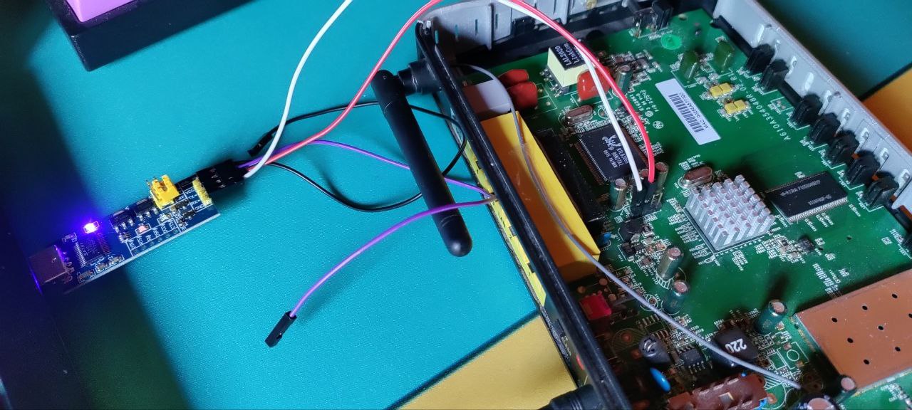
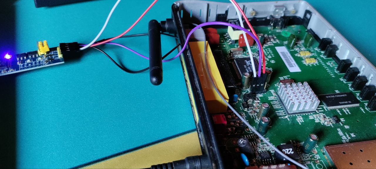
- Connect the board “TX” PIN with the RX PIN of the FT232RL
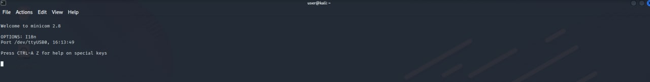
- Connect the FT232RL to the pc and open minicom
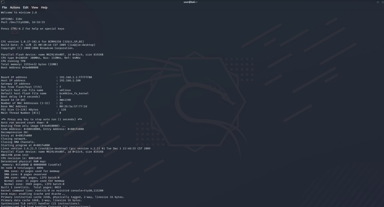
- Start the device. If it starts writing on the screen, it means that the PIN is the right one. If it writes unreadable characters it means that the pin is right but the baud rate is wrong
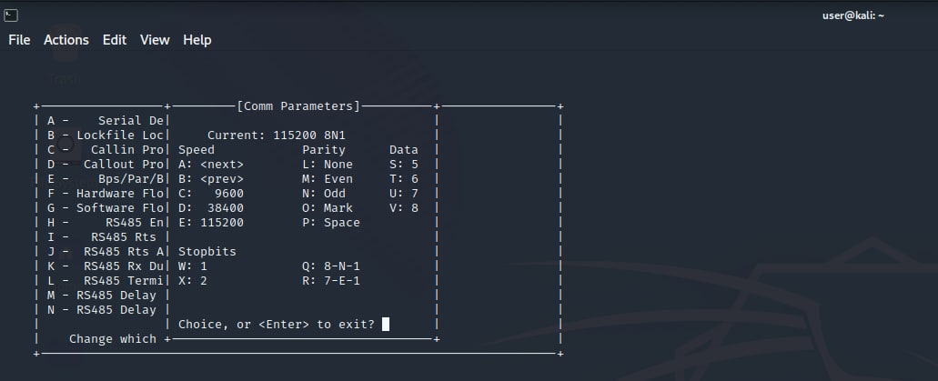
- Change the baud rate from minicom and restart the device
- Repeat until the correct baud rate is found
Wrong board “TX” pin:
Starting the device doesn’t print nothing:
Correct board “TX” pin but wrong baud rate:
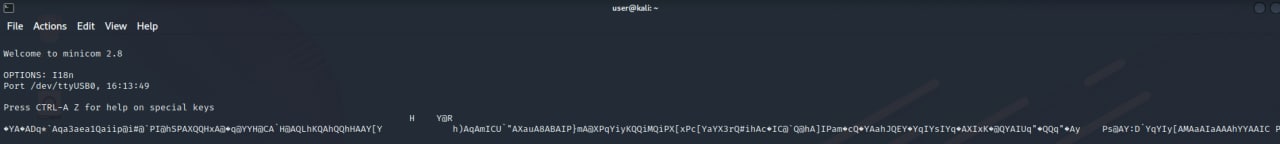
Change baud rate (in this case the correct was 115200):
Restart the device:
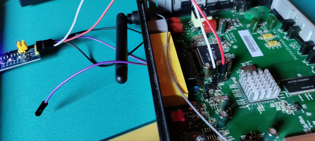
IDENTIFY THE RECEIVER
At this point we just need to connect the TX PIN of the FT232RL with one of the 2 remaining pins and try to write. Otherwise, you can identify it because it has the lowest voltage fluctuation and lowest overall value of all the UART pins.
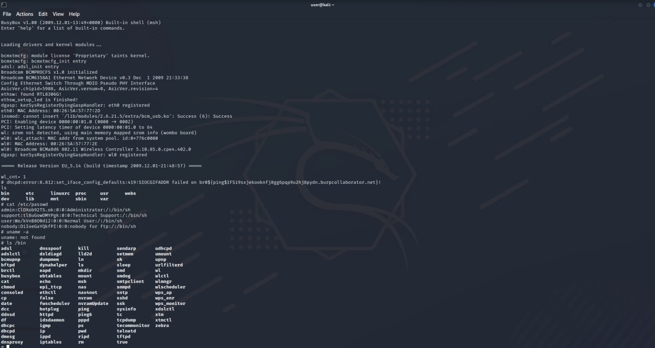
SHELL
REFERENCES
- PRACTICAL IOT HACKING The Definitive Guide to Attacking the Internet of Things
- https://www.analog.com/en/analog-dialogue/articles/uart-a-hardware-communication-protocol.html
- http://static.gest.unipd.it/~buso/mc_&_DSP_Lezioni/Lezione_21_(2_x_pagina).pdf